
BMS Wiring Diagram
BMS Wiring Diagram
Complete BMS Wiring Diagram Guide for Lithium-ion & LiFePO₄ Battery Packs
A Battery Management System (BMS) protects lithium battery packs from overcharging, over-discharging, overcurrent, short circuits, and excessive temperatures. It also monitors individual cell voltages and performs balancing (when supported) to improve battery life and performance.
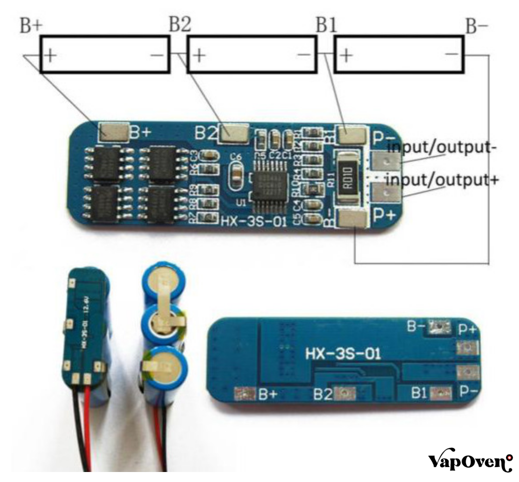
Below is a simplified common-port BMS wiring diagram, which is common for many lithium battery packs.
Basic BMS Wiring Diagram (Common-Port)
              Battery Pack

B+ -------------------------------------------> Load + / Charger +

Cell 4 (+) ------------------------ B4
                  │
Cell 3 (+) ------------------------ B3
                  │
Cell 2 (+) ------------------------ B2
                  │
Cell 1 (+) ------------------------ B1
                  │
Cell 1 (-) ------------------------ B0

Battery Negative ------------------ B-

                      ┌──────────────────────┐
                      │        BMS           │
                      │                      │
Battery Negative ---->│ B-              P-  │-------> Load Negative
Balance Connector --->│ B0 B1 B2 B3 B4      │
Temperature Sensor -->│ NTC (Optional)       │
CAN/RS485/UART ------>│ Communication        │
                      └──────────────────────┘
Typical Balance Wire Sequence (4S Example)
| Balance Wire | Connection |
|---|---|
| B0 | Battery Pack Negative (Cell 1 Negative) |
| B1 | Cell 1 Positive |
| B2 | Cell 2 Positive |
| B3 | Cell 3 Positive |
| B4 | Cell 4 Positive (Battery Positive) |
Important: Always connect balance wires in the exact order specified by the BMS manufacturer. Incorrect wiring can permanently damage the BMS.
Common BMS Terminals
| Terminal | Description |
|---|---|
| B- | Battery Pack Negative |
| B+ | Battery Pack Positive (usually connected directly to the battery positive) |
| P- | Load & Charger Negative (Common Port) |
| P+ | Load & Charger Positive (usually battery positive) |
| C- | Charger Negative (Separate-Port BMS only) |
| Balance Connector | Cell Voltage Monitoring |
| NTC | Temperature Sensor |
| CAN | CAN Bus Communication |
| RS485 | Industrial Communication |
| UART | Configuration & Monitoring |
| Bluetooth | Wireless Monitoring (Optional) |
Common-Port vs Separate-Port BMS
Common-Port BMS
- One negative terminal (P-) for charging and discharging.
- Simpler wiring.
- Commonly used in EVs, portable power stations, UPS systems, and energy storage.
Separate-Port BMS
- Separate negative terminals:
- P- → Discharge
- C- → Charging
- Often used in higher-power or application-specific battery systems.
General Installation Steps
- Assemble and inspect the battery pack.
- Measure each cell group’s voltage.
- Connect B- to the battery negative.
- Connect balance wires in the correct sequence.
- Connect P- (and C-, if applicable).
- Install temperature sensor (if used).
- Verify all voltages with a multimeter.
- Test charging and discharging functions.
Safety Precautions
- Disconnect all power sources before wiring.
- Never reverse battery polarity.
- Verify balance wire sequence before plugging into the BMS.
- Use insulated tools and appropriate PPE.
- Ensure wire sizes match the expected current.
- Follow the BMS manufacturer’s wiring instructions and ratings.
Applications
- Electric Bikes (E-Bikes)
- Electric Scooters
- Electric Motorcycles
- Electric Cars
- UPS Systems
- Solar Energy Storage
- Portable Power Stations
- Robotics
- Drones
- Marine Battery Systems
- Industrial Battery Packs
Frequently Asked Questions (FAQ)
Can I use the same BMS for LiFePO₄ and Lithium-ion batteries?
Generally, no. The BMS should be designed or configured for the battery chemistry because voltage limits and protection thresholds differ.
What happens if balance wires are connected incorrectly?
Incorrect balance wire connections can damage the BMS and potentially damage the battery pack. Always verify the sequence before connecting.
Do all BMS units have CAN Bus or Bluetooth?
No. These features are typically available only on Smart BMS models.
Contact Us
Lion Battery
📞 Phone / WhatsApp: +91-9724991737
📧 Email: info@lionbattery.in
🌐 Website: https://lionbattery.in